Schneider
ATV650D75N4 Schneider Electric
ATV650D75N4 Schneider Electric
Verfügbarkeit für Abholungen konnte nicht geladen werden
Industrial AC servo-drive hardware supplied by Outdwella.
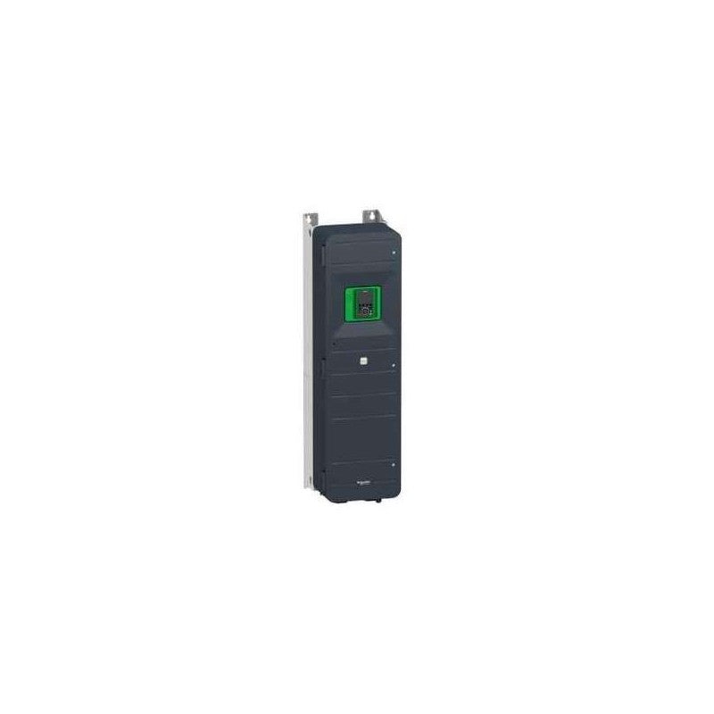
This Altivar Process ATV600 variable speed drive can feed 3-phase synchronous and asynchronous power motors. It features 3 built-in RJ45 communication ports as standard, 1 Ethernet port, 2 serial ports. It works at a rated supply voltage from 380V to 480V AC. This drive provides up to 30% energy saving when on standby due to the innovative ââStop and Goââoperation without additional costs. It is suitable for motors with power rating up to 75kW / 100hp for applications requiring slight overload (up to 120%). It is suitable for motors with power rating up to 55kW / 75hp for applications requiring significant overload (up to 150%). It weighs 87kg and its dimensions are, 345mm wide, 1250mm high, 375mm deep. This drive is focused on fluids management processing and energy saving, it offers extensive flexibility in water and wastewater, mining, minerals and metals, oil and gas and food and beverage applications. Accessories (fan kit, graphic display terminal) and options (I/O expansion modules, communication modules, EMC input filters) are available with Altivar Process ATV600 drives, depending on the drive rating. It is designed to be mounted in vertical position (+/- 10 °) on a wall. This new concept of drives meets the major needs of process and utilities in terms of equipment efficiency and total cost of ownership by supporting the energy management, asset management and also the overall performance of the process.
Main
| Characteristic | Value(s) |
|---|---|
| Range of product | Altivar Process ATV600 |
| Product specific application | Process and utilities |
| Product or component type | Variable speed drive |
| Variant | Standard version |
| Device short name | ATV650 |
| Mounting mode | Wall mount |
| Communication port protocol | Modbus TCP Ethernet Modbus TCP |
| [Us] rated supply voltage | 380...480 V - 15...10 % |
| [Us] rated supply voltage | 380...480 V |
| Relative symmetric mains voltage tolerance | 10 % |
| Relative symmetric network frequency tolerance | 5 % |
| nominal output current | 145.0 A |
| IP degree of protection | IP55 |
| Product destination | Asynchronous motors Synchronous motors |
| EMC filter | Integrated with 150 m conforming to IEC 61800-3 category C3 |
| IP degree of protection | IP55 conforming to IEC 60529 IP55 conforming to IEC 61800-5-1 |
| type of cooling | Forced convection |
| Supply frequency | 50...60 Hz - 5...5 % |
| Motor power kW | 55 kW (heavy duty) 75 kW (normal duty) |
| Motor power hp | 60 hp heavy duty 100 hp normal duty |
| Line current | 84.2 A at 480 V (normal duty) 81.4 A at 380 V (heavy duty) 71.8 A at 480 V (heavy duty) 131.3 A at 380 V (normal duty) |
| Continuous output current | 87 A for heavy duty 145 A at 2.5 kHz for normal duty |
| Speed drive output frequency | 0.1â¦500 Hz |
| Safety function | STO (safe torque off) SIL 3 |
| Option card | Slot A: communication module, PROFINET Slot A: communication module, DeviceNet Slot A: communication module, Modbus TCP/EtherNet/IP Slot A: communication module, CANopen daisy chain RJ45 Slot A: communication module, CANopen SUB-D 9 Slot A: communication module, CANopen screw terminals Slot A/slot B: digital and analog I/O extension module Slot A/slot B: output relay extension module Slot A: communication module, Ethernet IP/Modbus TCP/MD-Link Communication module, BACnet MS/TP Communication module, Ethernet Powerlink Slot A: communication module, Profibus DP V1 |
Complementary
| Characteristic | Value(s) |
|---|---|
| Discrete input number | 8 |
| Discrete input type | DI7, DI8 programmable as pulse input: 0â¦30 kHz, 24 V DC (<= 30 V) |
| Discrete input logic | 16 preset speeds |
| Discrete output number | 0 |
| Discrete output type | Relay outputs R1A, R1B, R1C 250 V AC 3000 mA Relay outputs R1A, R1B, R1C 30 V DC 3000 mA Relay outputs R2A, R2C 250 V AC 5000 mA Relay outputs R2A, R2C 30 V DC 5000 mA Relay outputs R3A, R3C 250 V AC 5000 mA Relay outputs R3A, R3C 30 V DC 5000 mA |
| Analogue input number | 3 |
| Analogue input type | AI1, AI2, AI3 software-configurable voltage: 0...10 V DC, impedance: 31.5 kOhm, resolution 12 bits AI1, AI2, AI3 software-configurable current: 0...20 mA, impedance: 250 Ohm, resolution 12 bits AI2 voltage analog input: - 10...10 V DC, impedance: 31.5 kOhm, resolution 12 bits |
| Analogue output number | 2 |
| Analogue output type | Software-configurable voltage AQ1, AQ2: 0...10 V DC impedance 470 Ohm, resolution 10 bits Software-configurable current AQ1, AQ2: 0...20 mA, resolution 10 bits Software-configurable current DQ-, DQ+: 30 V DC Software-configurable current DQ-, DQ+: 100 mA |
| Relay output number | 3 |
| Relay output type | Configurable relay logic R2: sequence relay NO electrical durability 100000 cycles Configurable relay logic R3: sequence relay NO electrical durability 100000 cycles Configurable relay logic R1: fault relay NO/NC electrical durability 100000 cycles |
| Maximum switching current | Relay output R1, R2, R3 on resistive load, cos phi = 1: 3 A at 30 V DC Relay output R1, R2, R3 on inductive load, cos phi = 0.4 and L/R = 7 ms: 2 A at 250 V AC Relay output R1, R2, R3 on inductive load, cos phi = 0.4 and L/R = 7 ms: 2 A at 30 V DC Relay output R1, R2, R3 on resistive load, cos phi = 1: 3 A at 250 V AC |
| Minimum switching current | Relay output R1, R2, R3: 5 mA at 24 V DC |
| Network number of phases | 3 phases |
| Physical interface | Ethernet 2-wire RS 485 |
| Method of access | Slave Modbus TCP |
| Transmission rate | 10, 100 Mbits 4800 bps, 9600 bps, 19200 bps, 38.4 Kbps |
| Transmission frame | RTU |
| Output voltage | <= power supply voltage |
| Permissible temporary current boost | 1.5 x In during 60 s (heavy duty) 1.1 x In during 60 s (normal duty) |
| Data format | 8 bits, configurable odd, even or no parity |
| Type of polarization | No impedance |
| Frequency resolution | Analog input: 0.012/50 Hz Display unit: 0.1 Hz |
| Electrical connection | Motor: screw terminal 70...120 mm²/AWG 1/0...250 kcmil Line side: screw terminal 70...95 mm²/AWG 1...250 kcmil Control: removable screw terminals 0.5...1.5 mm²/AWG 20...AWG 16 |
| Connector type | RJ45 (on the remote graphic terminal) for Modbus serial RJ45 (on the remote graphic terminal) for Ethernet/Modbus TCP |
| Exchange mode | Half duplex, full duplex, autonegotiation Ethernet/Modbus TCP |
| Number of addresses | 1â¦247 for Modbus serial |
| Supply | Internal supply for reference potentiometer (1 to 10 kOhm): 10.5 V DC +/- 5 %, <10 mA, protection type: overload and short-circuit protection Internal supply for digital inputs and STO: 24 V DC (21â¦27 V), <200 mA, protection type: overload and short-circuit protection External supply for digital inputs: 24 V DC (19â¦30 V), <1.25 mA, protection type: overload and short-circuit protection |
| Local signalling | 3 LEDs (dual colour) for embedded communication status 4 LEDs (dual colour) for communication module status 1 LED (red) for presence of voltage 3 LEDs for local diagnostic |
| Input compatibility | DI5, DI6: discrete input level 1 PLC conforming to IEC 65A-68 STOA, STOB: discrete input level 1 PLC conforming to IEC 61131-2 DI1...DI6: discrete input level 1 PLC conforming to IEC 61131-2 |
| Discrete input logic | Positive logic (source) (DI1...DI8), < 5 V (state 0), > 11 V (state 1) Negative logic (sink) (DI1...DI8), > 16 V (state 0), < 10 V (state 1) |
| Sampling duration | 5 ms +/- 1 ms (DI5, DI6) - discrete input 5 ms +/- 0.1 ms (AI1, AI2, AI3) - analog input 10 ms +/- 1 ms (AO1) - analog output 2 ms +/- 0.5 ms (DI1...DI4) - discrete input |
| Accuracy | +/- 1 % AO1, AO2 for a temperature variation 60 °C analog output +/- 0.6 % AI1, AI2, AI3 for a temperature variation 60 °C analog input |
| Linearity error | AO1, AO2: +/- 0.2 % for analog output AI1, AI2, AI3: +/- 0.15 % of maximum value for analog input |
| Refresh time | Relay output (R1, R2, R3): 5 ms (+/- 0.5 ms) |
| Isolation | Between power and control terminals |
| Discrete and process manufacturing | Building - HVAC compressor centrifugal |
| Power range | 55â¦100 kW at 380â¦440 V 3 phases |
| Enclosure mounting | Wall mounted |
| 4 quadrant operation possible | False |
| Asynchronous motor control profile | Constant torque standard Optimized torque mode Optimized torque mode |
| Synchronous motor control profile | Synchronous reluctance motor Permanent magnet motor |
| Maximum output frequency | 500 kHz |
| Acceleration and deceleration ramps | Linear adjustable separately from 0.01...9999 s |
| Motor slip compensation | Not available in permanent magnet motor law Adjustable Can be suppressed Adjustable |
| Switching frequency | 2...8 kHz adjustable 2.5...8 kHz with derating factor |
| Nominal switching frequency | 2.5 kHz |
| Braking to standstill | By DC injection |
| Brake chopper integrated | False |
| Maximum input current | 131.3 A |
| Maximum output voltage | 480.0 V |
| Apparent power | 59.7 kVA at 480 V (heavy duty) 93.7 kVA at 480 V (normal duty) |
| Maximum transient current | 132 A during 60 s (heavy duty) 159.5 A during 60 s (normal duty) |
| Network frequency | 50...60 Hz |
| Prospective line Isc | 50 kA |
| Base load current at high overload | 106.0 A |
| Base load current at low overload | 145.0 A |
| With safety function Safely Limited Speed (SLS) | False |
| With safety function Safe brake management (SBC/SBT) | False |
| With safety function Safe Operating Stop (SOS) | False |
| With safety function Safe Position (SP) | False |
| With safety function Safe programmable logic | False |
| With safety function Safe Speed Monitor (SSM) | False |
| With safety function Safe Stop 1 (SS1) | False |
| With sft fct Safe Stop 2 (SS2) | False |
| With safety function Safe torque off (STO) | True |
| With safety function Safely Limited Position (SLP) | False |
| With safety function Safe Direction (SDI) | False |
| Protection type | Safe torque off: motor Motor phase break: motor Thermal protection: drive Safe torque off: drive Overheating: drive Overcurrent between output phases and earth: drive Overload of output voltage: drive Short-circuit protection: drive Motor phase break: drive Overvoltages on the DC bus: drive Line supply overvoltage: drive Line supply undervoltage: drive Line supply phase loss: drive Overspeed: drive Break on the control circuit: drive Thermal protection: motor |
| Quantity per set | 1 |
| Width | 345 mm |
| Height | 1250 mm |
| Depth | 375 mm |
| Product weight | 87 kg |
Ordering notes
- New items are unused surplus stock and packaging condition may vary.
- Used in Great Condition items have been previously installed or operated and are represented as serviceable used hardware.
- Confirm the complete manufacturer part number, input voltage, output rating, motor compatibility, feedback interface, revision, and control-system requirements.
Outdwella is an independent reseller. Manufacturer names and part numbers identify compatibility and remain the property of their respective owners.
Share