1
/
of
1
Schneider
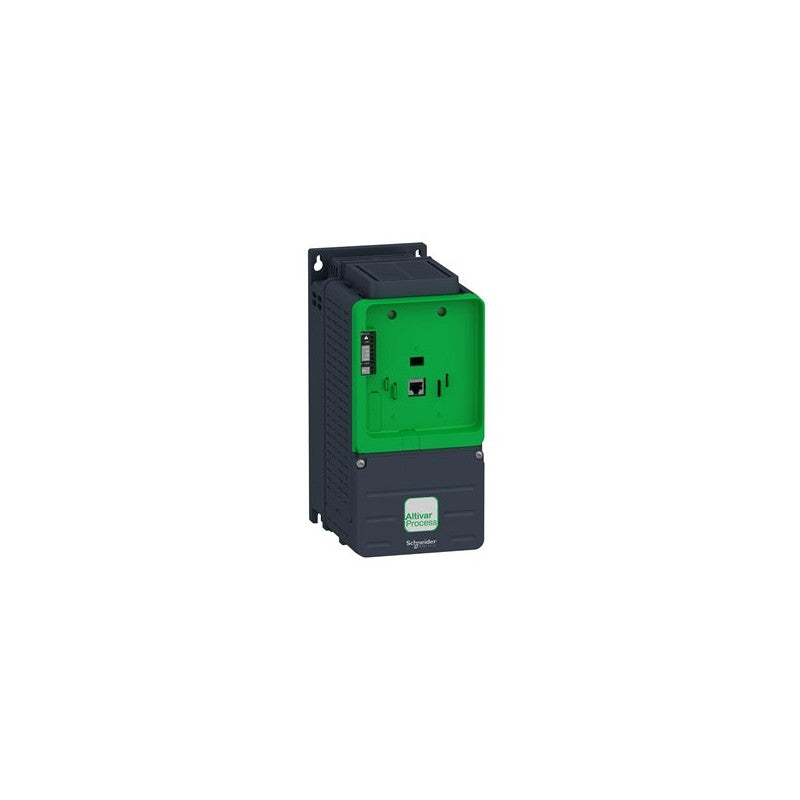
ATV930U30N4Z Schneider Electric
ATV930U30N4Z Schneider Electric
Regular price
$637.21 USD
Regular price
$749.66 USD
Sale price
$637.21 USD
Unit price
/
per
Tax included.
Shipping calculated at checkout.
Couldn't load pickup availability
Industrial AC servo-drive hardware supplied by Outdwella.
Main
| Characteristic | Value(s) |
|---|---|
| Range of Product | Altivar Process ATV900 |
| Device Application | Industrial Application |
| Product or Component Type | Variable speed drive |
| Product destination | Asynchronous motors Synchronous motors |
| Product Specific Application | Process for industrial |
| Variant | With braking chopper Standard version |
| Phase | 3 phase |
| Mounting Mode | Cabinet mount |
| Communication Port Protocol | Modbus serial EtherNet/IP Modbus TCP |
| [Us] rated supply voltage | 380...480 V - 15...10 % |
| Continuous output current | 7.2 A 4 kHz normal duty 5.6 A 4 kHz heavy duty |
| EMC filter | Integrated With EMC plate option |
| IP degree of protection | IP21 |
| option module | Slot A communication module Profibus DP V1 Slot A communication module PROFINET Slot A communication module DeviceNet Slot A communication module EtherCAT Slot A communication module CANopen daisy chain RJ45 Slot A communication module CANopen SUB-D 9 Slot A communication module CANopen screw terminals Slot A/slot B/slot C digital and analog I/O extension module Slot A/slot B/slot C output relay extension module Slot B 5/12 V digital encoder interface module Slot B analog encoder interface module Slot B resolver encoder interface module communication module Ethernet Powerlink |
| Discrete input logic | 16 preset speeds |
| Motor power kW | 3.0 kW normal duty 2.2 kW heavy duty |
| Asynchronous motor control profile | Variable torque standard Constant torque standard Optimized torque mode |
| Synchronous motor control profile | Permanent magnet motor Synchronous reluctance motor |
| Maximum output frequency | 599 Hz |
| Switching frequency | 2...16 kHz adjustable 4...16 kHz with derating factor |
| Nominal switching frequency | 4 kHz |
| Line current | 5.8 A 380 V normal duty) 4.5 A 380 V heavy duty) 5.1 A 480 V normal duty) 4.0 A 480 V heavy duty) |
| Apparent power | 4.2 kVA 480 V normal duty) 3.3 kVA 480 V heavy duty) |
| Maximum transient current | 8.6 A 60 s normal duty) 8.4 A 60 s heavy duty) |
| Network Frequency | 50-60 Hz |
| Prospective line Isc | 50 kA |
Complementary
| Characteristic | Value(s) |
|---|---|
| Discrete input number | 10 |
| Discrete input type | DI1...DI8 programmable, 24 V DC <= 30 V)3.5 kOhm DI7, DI8 programmable as pulse input 0â¦30 kHz, 24 V DC <= 30 V) STOA, STOB safe torque off, 24 V DC <= 30 V)> 2.2 kOhm |
| Discrete output number | 2 |
| Discrete output type | Logic output DQ+ 0â¦1 kHz <= 30 V DC 100 mA Programmable as pulse output DQ+ 0â¦30 kHz <= 30 V DC 20 mA Logic output DQ- 0â¦1 kHz <= 30 V DC 100 mA |
| Analogue input number | 3 |
| Analogue input type | AI1, AI2, AI3 software-configurable voltage 0...10 V DC 30 kOhm 12 bits AI1, AI2, AI3 software-configurable current 0...20 mA/4...20 mA 250 Ohm 12 bits |
| Analogue output number | 2 |
| Analogue output type | Software-configurable voltage AQ1, AQ2 0...10 V DC 470 Ohm 10 bits Software-configurable current AQ1, AQ2 0...20 mA 500 Ohm 10 bits |
| Relay output number | 3 |
| Relay output type | Configurable relay logic R1 fault relay NO/NC 100000 cycles Configurable relay logic R2 sequence relay NO 1000000 cycles Configurable relay logic R3 sequence relay NO 1000000 cycles |
| Maximum switching current | Relay output R1 resistive, cos phi = 1 3 A 250 V AC Relay output R1 resistive, cos phi = 1 3 A 30 V DC Relay output R1 inductive, cos phi = 0.4 7 ms 2 A 250 V AC Relay output R1 inductive, cos phi = 0.4 7 ms 2 A 30 V DC Relay output R2, R3 resistive, cos phi = 1 5 A 250 V AC Relay output R2, R3 resistive, cos phi = 1 5 A 30 V DC Relay output R2, R3 inductive, cos phi = 0.4 7 ms 2 A 250 V AC Relay output R2, R3 inductive, cos phi = 0.4 7 ms 2 A 30 V DC |
| Minimum switching current | Relay output R1, R2, R3 5 mA 24 V DC |
| Physical interface | Ethernet 2-wire RS 485 |
| Connector Type | 2 RJ45 1 RJ45 |
| Method of access | Slave Modbus TCP |
| Transmission Rate | 10, 100 Mbits 4.8 kbps 9600 bit/s 19200 bit/s |
| Transmission frame | RTU |
| Number of addresses | 1â¦247 |
| Data format | 8 bits, configurable odd, even or no parity |
| Type of polarization | No impedance |
| 4 quadrant operation possible | True |
| Acceleration and deceleration ramps | Linear adjustable separately from 0.01...9999 s |
| Motor slip compensation | Automatic whatever the load Not available in permanent magnet motor law Adjustable Can be suppressed |
| Braking to standstill | By DC injection |
| Brake chopper integrated | True |
| Maximum Input Current per Phase | 5.8 A |
| Maximum output voltage | 480.0 V |
| Relative symmetric network frequency tolerance | 5 % |
| Base load current at high overload | 5.6 A |
| Base load current at low overload | 7.2 A |
| Power dissipation in W | Natural convection 31 W 380 V 4 kHz Forced convection 78 W 380 V 4 kHz |
| With safety function Safely Limited Speed (SLS) | True |
| With safety function Safe brake management (SBC/SBT) | True |
| With safety function Safe Operating Stop (SOS) | False |
| With safety function Safe Position (SP) | False |
| With safety function Safe programmable logic | False |
| With safety function Safe Speed Monitor (SSM) | False |
| With safety function Safe Stop 1 (SS1) | True |
| With sft fct Safe Stop 2 (SS2) | False |
| With safety function Safe torque off (STO) | True |
| With safety function Safely Limited Position (SLP) | False |
| With safety function Safe Direction (SDI) | False |
| Protection type | Thermal protection motor Safe torque off motor Motor phase break motor Thermal protection drive Safe torque off drive Overheating drive Overcurrent between output phases and earth drive Overload of output voltage drive Short-circuit protection drive Motor phase break drive Overvoltages on the DC bus drive Line supply overvoltage drive Line supply undervoltage drive Line supply phase loss drive Overspeed drive Break on the control circuit drive |
| Quantity per Set | 1 |
| Width | 5.1 in (130 mm) |
| Height | 11.2 in (285 mm) |
| Depth | 7.7 in (196 mm) |
| Electrical connection | Control screw terminal 0.5...1.5 mm² AWG 20...AWG 16 Line side screw terminal 2.5...6 mm² AWG 14...AWG 10 Motor screw terminal 2.5...6 mm² AWG 14...AWG 10 DC bus screw terminal 2.5...6 mm² AWG 14...AWG 10 |
| Transmission Rate | 10/100 Mbit/s Ethernet IP/Modbus TCP 4.8, 9.6, 19.2, 38.4 kbit/s Modbus serial |
| Exchange mode | Half duplex, full duplex, autonegotiation Ethernet IP/Modbus TCP |
| Data format | 8 bits, configurable odd, even or no parity Modbus serial |
| Type of polarization | No impedance Modbus serial |
| Number of addresses | 1â¦247 Modbus serial |
| Supply | External supply for digital inputs 24 V DC 19â¦30 V), <1.25 mA overload and short-circuit protection Internal supply for reference potentiometer (1 to 10 kOhm) 10.5 V DC +/- 5 %, <10 mA overload and short-circuit protection Internal supply for digital inputs and STO 24 V DC 21â¦27 V), <200 mA overload and short-circuit protection |
| Local signalling | Local diagnostic: 3 LED (mono/dual colour) Embedded communication status: 5 LED (dual colour) Communication module status: 2 LED (dual colour) Presence of voltage: 1 LED (red) |
| Input compatibility | DI1...DI8 discrete input level 1 PLC IEC 61131-2 DI7, DI8 pulse input level 1 PLC IEC 65A-68 STOA, STOB discrete input level 1 PLC IEC 61131-2 |
| Discrete input logic | Positive logic (source) DI1...DI8), < 5 V, > 11 V Negative logic (sink) DI1...DI8), > 16 V, < 10 V Positive logic (source) DI7, DI8), < 0.6 V, > 2.5 V Positive logic (source) STOA, STOB), < 5 V, > 11 V |
| Sampling duration | 2 ms +/- 0.5 ms DI1...DI8) - discrete input 5 ms +/- 1 ms DI7, DI8) - pulse input 1 ms +/- 1 ms AI1, AI2, AI3) - analog input 5 ms +/- 1 ms AQ1, AQ2) - analog output |
| Accuracy | +/- 0.6 % AI1, AI2, AI3 for a temperature variation 60 °C analog input +/- 1 % AQ1, AQ2 for a temperature variation 60 °C analog output |
| Linearity error | AI1, AI2, AI3 +/- 0.15 % of maximum value analog input AQ1, AQ2 +/- 0.2 % analog output |
| Refresh time | Relay output R1, R2, R3)5 ms +/- 0.5 ms) |
| Isolation | Between power and control terminals |
Ordering notes
- New items are unused surplus stock and packaging condition may vary.
- Used in Great Condition items have been previously installed or operated and are represented as serviceable used hardware.
- Confirm the complete manufacturer part number, input voltage, output rating, motor compatibility, feedback interface, revision, and control-system requirements.
Outdwella is an independent reseller. Manufacturer names and part numbers identify compatibility and remain the property of their respective owners.
Share