Schneider
ATV32HU55N4 Schneider
ATV32HU55N4 Schneider
Couldn't load pickup availability
Industrial AC servo-drive hardware supplied by Outdwella.
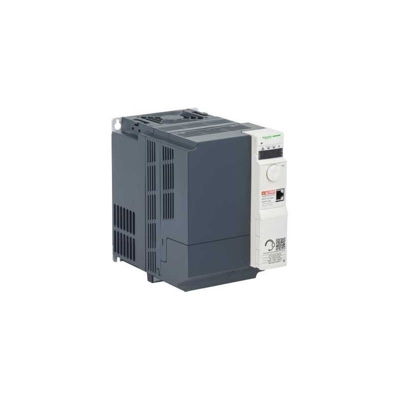
This Altivar 32 3-phase variable speed drive has a rated power of 5.5kW, and a supply voltage of 380V to 500V AC. It is designed for applications such as small conveyors, hoists, bagging / labeling machines, mixers, kneaders, textile machines, pumps, compressors, fans, wood-working and metal processing machines. It has a 150mm-wide compact form-factor, allowing for a flexible and easy installation on a mounting plate without any space between adjacent drives. It also offers a snap-lock seal, status and faults display, a jog dial navigation button and an integrated EMC filter. It offers high readability of key parameters thanks to a bright LED 4-digit display. SoMove software compatibility enables saving and transfering of configurations to spare drive, reducing maintenance downtime.
Main
| Characteristic | Value(s) |
|---|---|
| Range of Product | Altivar 32 |
| Product or Component Type | Variable speed drive |
| Product destination | Synchronous motors Asynchronous motors |
| Product Specific Application | Complex machines |
| Function Available | - |
| Assembly style | With heat sink |
| Component name | ATV32 |
| EMC filter | Class C2 EMC filter integrated |
| Phase | 3 phase |
| [Us] rated supply voltage | 380...500 V - 15...10 % |
| Supply voltage limits | 323â¦550 V |
| Supply frequency | 50...60 Hz - 5...5 % |
| Network Frequency | 47.5...63 Hz |
| Motor power kW | 5.5 kW 380...480 V |
| Maximum Horse Power Rating | 7.5 hp 380...480 V |
Complementary
| Characteristic | Value(s) |
|---|---|
| Line current | 14.5 A 500 V 3 phase 5.5 kW / 7.5 hp 20.7 A 380 V 3 phase 5.5 kW / 7.5 hp |
| Apparent power | 17.9 kVA 500 V 3 phase 5.5 kW / 7.5 hp |
| Prospective line Isc | 22 kA 3 phase |
| Nominal output current | 14.3 A 4 kHz 500 V 5.5 kW / 7.5 hp |
| Maximum transient current | 21.5 A 60 s 5.5 kW / 7.5 hp |
| Output frequency | 0.0005â¦0.599 kHz |
| Nominal switching frequency | 4 kHz |
| Switching frequency | 2...16 kHz adjustable |
| Speed range | 1â¦100 asynchronous motor in open-loop mode |
| Speed accuracy | +/- 10 % of nominal slip 0.2 Tn to Tn |
| Torque accuracy | +/- 15 % |
| Transient overtorque | 170â¦200 % |
| Braking torque | <= 170 % with braking resistor |
| Asynchronous motor control profile | Flux vector control without sensor, standard Flux vector control without sensor - Energy Saving, NoLoad law Voltage/frequency ratio, 5 points Voltage/frequency ratio - Energy Saving, quadratic U/f Voltage/frequency ratio, 2 points |
| Synchronous motor control profile | Vector control without sensor |
| Regulation loop | Adjustable PID regulator |
| Motor slip compensation | Automatic whatever the load Adjustable 0...300 % Not available in voltage/frequency ratio (2 or 5 points) |
| Local signalling | 1 LED red drive voltage 1 LED green CANopen run 1 LED red CANopen error 1 LED red drive fault |
| Output voltage | <= power supply voltage |
| Noise level | 43 dB 86/188/EEC |
| Insulation | Electrical between power and control |
| Electrical connection | Screw terminal 0.5...1.5 mm², AWG 18...AWG 14 control) Removable screw terminals 2.5...16 mm², AWG 12...AWG 6 motor/braking resistor) Screw terminal 4...16 mm², AWG 10...AWG 6 power supply) |
| Tightening torque | 4.4 lbf.in (0.5 N.m), 4.4 lb/ft control) 10.6 lbf.in (1.2 N.m), 10.6 lb/ft motor/braking resistor) 10.6 lbf.in (1.2 N.m), 10.6 lb/ft power supply) |
| Supply | Internal supply for reference potentiometer (1 to 10 kOhm) 10.5 V DC +/- 5 %, <10 mA overload and short-circuit protection |
| Analogue input number | 3 |
| Analogue input type | AI1 voltage 0...10 V DC 30000 Ohm 10 bits AI2 bipolar differential voltage +/- 10 V DC 30000 Ohm 10 bits AI3 current 0...20 mA (or 4-20 mA, x-20 mA, 20-x mA or other patterns by configuration) 250 Ohm 10 bits |
| Sampling duration | 2 ms AI1, AI2, AI3) - analog 2 ms AO1) - analog |
| Response time | LI1...LI6 8 ms +/- 0.7 ms logic R1A, R1B, R1C 2 ms relay R2A, R2C 2 ms relay |
| Accuracy | +/- 0.2 % AI1, AI2, AI3) for a temperature of -10...60 °C +/- 0.5 % AI1, AI2, AI3) for a temperature of 25 °C +/- 1 % AO1) for a temperature of 25 °C +/- 2 % AO1) for a temperature of -10...60 °C |
| Linearity error | +/- 0.2...0.5 % of maximum value AI1, AI2, AI3) +/- 0.3 % AO1) |
| Analogue output number | 1 |
| Analogue output type | AO1 software-configurable current 0...20 mA 800 Ohm 10 bits AO1 software-configurable voltage 0...10 V 470 Ohm 10 bits |
| Discrete output number | 3 |
| Discrete output type | Configurable relay logic R1A, R1B, R1C) NO/NC - 100000 cycles Configurable relay logic R2A, R2B) NO - 100000 cycles Logic LO) |
| Minimum switching current | 5 mA 24 V DC configurable relay logic |
| Maximum switching current | R1 3 A 250 V AC resistive, cos phi = 1 R1 4 A 30 V DC resistive, cos phi = 1 R1, R2 2 A 250 V AC inductive, cos phi = 0.4 R1, R2 2 A 30 V DC inductive, cos phi = 0.4 R2 5 A 250 V AC resistive, cos phi = 1 R2 5 A 30 V DC resistive, cos phi = 1 |
| Discrete input number | 7 |
| Discrete input type | Programmable (sink/source) LI1...LI4)24...30 V DC level 1 PLC Programmable as pulse input 20 kpps LI5)24...30 V DC level 1 PLC Switch-configurable PTC probe LI6)24...30 V DC Safe torque off STO)24...30 V DC - 1500 Ohm |
| Discrete input logic | Negative logic (sink) LI1...LI6), > 19 V, < 13 V Positive logic (source) LI1...LI6), < 5 V, > 11 V |
| Acceleration and deceleration ramps | Linear Ramp switching Deceleration ramp automatic stop DC injection CUS S U Deceleration ramp adaptation |
| Braking to standstill | By DC injection |
| Protection type | Input phase breaks drive Overcurrent between output phases and earth drive Overheating protection drive Short-circuit between motor phases drive Thermal protection drive |
| Communication Port Protocol | CANopen Modbus |
| Connector type | 1 RJ45 on front face)Modbus/CANopen |
| Physical interface | 2-wire RS 485 Modbus |
| Transmission frame | RTU Modbus |
| Type of polarization | No impedance Modbus |
| Number of addresses | 1â¦127 CANopen 1â¦247 Modbus |
| Method of access | Slave CANopen |
| Electromagnetic compatibility | 1.2/50 µs - 8/20 µs surge immunity test, level 3 IEC 61000-4-5 Conducted radio-frequency immunity test, level 3 IEC 61000-4-6 Electrical fast transient/burst immunity test, level 4 IEC 61000-4-4 Electrostatic discharge immunity test, level 3 IEC 61000-4-2 Radiated radio-frequency electromagnetic field immunity test, level 3 IEC 61000-4-3 Voltage dips and interruptions immunity test IEC 61000-4-11 |
| Width | 5.9 in (150 mm) |
| Height | 12.1 in (308 mm) |
| Depth | 9.1 in (232 mm) |
| Product Weight | 16.5 lb(US) (7.5 kg) |
| Option card | Communication card CANopen daisy chain Communication card CANopen open style Communication card DeviceNet Communication card EtherNet/IP Communication card Profibus DP V1 |
| Functionality | Mid |
| Specific application | Other applications |
Ordering notes
- New items are unused surplus stock and packaging condition may vary.
- Used in Great Condition items have been previously installed or operated and are represented as serviceable used hardware.
- Confirm the complete manufacturer part number, input voltage, output rating, motor compatibility, feedback interface, revision, and control-system requirements.
Outdwella is an independent reseller. Manufacturer names and part numbers identify compatibility and remain the property of their respective owners.
Share