Schneider
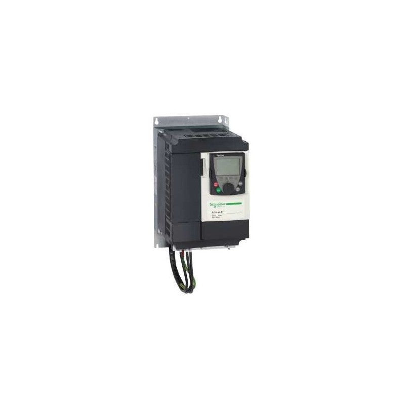
ATV71LD33M3Z Schneider Electric Altivar Lift Variable speed drive
ATV71LD33M3Z Schneider Electric Altivar Lift Variable speed drive
Precio habitual
$4,189.59 USD
Precio habitual
$4,928.93 USD
Precio de oferta
$4,189.59 USD
Precio unitario
/
por
Impuesto incluido.
Los gastos de envío se calculan en la pantalla de pago.
No se pudo cargar la disponibilidad de retiro
Industrial AC servo-drive hardware supplied by Outdwella.
Main
| Characteristic | Value(s) |
|---|---|
| Device short name | ATV71 |
| Product destination | Synchronous motors Asynchronous motors |
| Network number of phases | 3 phases |
| Supply voltage limits | 170â¦264 V |
| Supply frequency | 50...60 Hz - 5...5 % |
| Motor power kW | 7.5 kW, 3 phases at 200...240 V |
| Motor power hp | 10 hp, 3 phases at 200...240 V |
| Line current | 45 A for 200 V 3 phases 7.5 kW / 10 hp 39.4 A for 240 V 3 phases 7.5 kW / 10 hp |
| Range of product | Altivar Lift |
| Product or component type | Variable speed drive |
| Product specific application | Lift |
| Variant | With integrated 7-segment display terminal |
| Communication port protocol | CANopen Modbus |
| [Us] rated supply voltage | 200...240 V - 15...10 % |
Complementary
| Characteristic | Value(s) |
|---|---|
| Apparent power | 16.4 kVA at 240 V 3 phases 7.5 kW / 10 hp |
| Prospective line Isc | 22 kA for 3 phases |
| Nominal output current | 33 A at 4 kHz 230 V 3 phases 7.5 kW / 10 hp |
| Maximum transient current | 44.9 A for 2 s 3 phases / 7.5 kW / 10 hp |
| Speed drive output frequency | 0â¦599 Hz |
| Speed range | 1â¦100 for asynchronous motor in open-loop mode, without speed feedback 1â¦50 for synchronous motor in open-loop mode, without speed feedback 1â¦1000 for asynchronous motor in closed-loop mode with encoder feedback |
| Torque accuracy | +/- 5 % in closed-loop mode with encoder feedback +/- 15 % in open-loop mode, without speed feedback |
| Transient overtorque | 170 %, +/- 10 % for 60 s 220 %, +/- 10 % for 2 s |
| Braking torque | 30 % without braking resistor <= 150 % with braking or hoist resistor |
| Local signalling | 1 LED (red) for drive voltage |
| Output voltage | <= power supply voltage |
| Insulation | Electrical between power and control |
| type of cable for external connection | Without mounting kit: 1 wire(s)IEC cable at 45 °C, copper 90 °C / XLPE/EPR Without mounting kit: 1 wire(s)IEC cable at 45 °C, copper 70 °C / PVC With an IP21 or an IP31 kit: 3 wire(s)IEC cable at 40 °C, copper 70 °C / PVC With a NEMA Type1 kit: 3 wire(s)UL 508 cable at 40 °C, copper 75 °C / PVC |
| Electrical connection | Terminal, clamping capacity: 2.5 mm², AWG 14 (AI1-/AI1+, AI2, AO1, R1A, R1B, R1C, R2A, R2B, LI1...LI6, PWR) Terminal, clamping capacity: 16 mm², AWG 4 (L1/R, L2/S, L3/T, U/T1, V/T2, W/T3, PC/-, PO, PA/+, PA, PB) |
| Tightening torque | 3 N.m, 26.5 lb.in (L1/R, L2/S, L3/T, U/T1, V/T2, W/T3, PC/-, PO, PA/+, PA, PB) 0.6 N.m (AI1-/AI1+, AI2, AO1, R1A, R1B, R1C, R2A, R2B, LI1...LI6, PWR) |
| Supply | Internal supply for reference potentiometer (1 to 10 kOhm): 10.5 V DC +/- 5 %, <10 A, protection type: overload and short-circuit protection Internal supply: 24 V DC (21â¦27 V), <200 A, protection type: overload and short-circuit protection |
| Sampling duration | 2 ms +/- 0.5 ms (LI6)if configured as logic input - discrete input(s) 2 ms +/- 0.5 ms (LI1...LI5) - discrete input(s) 2 ms +/- 0.5 ms (AI1-/Al1+) - analog input(s) 2 ms +/- 0.5 ms (Al2) - analog input(s) |
| Response time | R1A, R1B, R1C 7 ms, tolerance +/- 0.5 ms for discrete output(s) R2A, R2B 7 ms, tolerance +/- 0.5 ms for discrete output(s) AO1 2 ms, tolerance +/- 0.5 ms for analog output(s) <= 100 ms in STO (Safe Torque Off) |
| Accuracy | +/- 0.6 % (AI1-/Al1+) for a temperature variation 60 °C +/- 0.6 % (AI2) for a temperature variation 60 °C +/- 1 % (AO1) for a temperature variation 60 °C |
| Linearity error | +/- 0.15 % of maximum value (AI1-/Al1+, AI2) +/- 0.2 % (AO1) |
| Analogue output type | AO1 software-configurable voltage: 0...10 V DC, impedance: 470 Ohm, resolution 10 bits AO1 software-configurable current: 0...20 mA, impedance: 500 Ohm, resolution 10 bits AO1 software-configurable logic output 10 V 20 A |
| Discrete output type | Configurable relay logic: (R1A, R1B, R1C) NO/NC - 100000 cycles Configurable relay logic: (R2A, R2B) NO - 100000 cycles |
| Minimum switching current | 3 mA at 24 V DC for configurable relay logic |
| Maximum switching current | 5 A at 250 V AC on resistive load - cos phi = 1 - L/R = 0 ms (R1, R2) 5 A at 30 V DC on resistive load - cos phi = 1 - L/R = 0 ms (R1, R2) 2 A at 250 V AC on inductive load - cos phi = 0.4 - L/R = 7 ms (R1, R2) 2 A at 30 V DC on inductive load - cos phi = 0.4 - L/R = 7 ms (R1, R2) |
| Discrete input type | Programmable (LI1...LI5)24 V DC, with level 1 PLC - 3500 Ohm Switch-configurable (LI6)24 V DC, with level 1 PLC - 3500 Ohm Switch-configurable PTC probe (LI6) - 0â¦6 probes - 1500 Ohm Safety input (PWR)24 V DC - 1500 Ohm |
| Discrete input logic | Positive logic (LI6)if configured as logic input, < 5 V (state 0), > 11 V (state 1) Negative logic (LI6)if configured as logic input, > 16 V (state 0), < 10 V (state 1) Positive logic (LI1...LI5), < 5 V (state 0), > 11 V (state 1) Negative logic (LI1...LI5), > 16 V (state 0), < 10 V (state 1) Positive logic (PWR), < 2 V (state 0), > 17 V (state 1) |
| Dielectric strength | 2830 V DC between earth and power terminals 4230 V DC between control and power terminals |
| Insulation resistance | > 1 mOhm 500 V DC for 1 minute to earth |
| Frequency resolution | Display unit: 0.1 Hz Analog input: 0.024/50 Hz |
| Connector type | 1 RJ45 (on front face) for Modbus 1 RJ45 (on terminal) for Modbus Male SUB-D 9 on RJ45 for CANopen |
| Physical interface | 2-wire RS 485 for Modbus |
| Transmission frame | RTU for Modbus |
| Transmission rate | 9600 bps, 19200 bps for Modbus on front face 4800 bps, 9600 bps, 19200 bps, 38.4 Kbps for Modbus on terminal 20 kbps, 50 kbps, 125 kbps, 250 kbps, 500 kbps, 1 Mbps for CANopen |
| Data format | 8 bits, 1 stop, even parity for Modbus on front face 8 bits, odd even or no configurable parity for Modbus on terminal |
| Type of polarization | No impedance for Modbus |
| Number of addresses | 1â¦247 for Modbus 1â¦127 for CANopen |
| control options | Communication card for Modbus TCP Communication card for Fipio Communication card for Modbus/Uni-Telway Communication card for Modbus Plus Communication card for EtherNet/IP Communication card for DeviceNet Communication card for Profibus DP Communication card for Profibus DP V1 Communication card for Interbus-S Communication card for CC-Link Interface card for encoder I/O extension card Controller inside programmable card Overhead crane card |
| Discrete input number | 7 |
| Discrete output number | 2 |
| Analogue input number | 2 |
| Analogue input type | AI2 software-configurable voltage: 0...10 V DC 24 V max, impedance: 30000 Ohm, resolution 11 bits AI1-/Al1+ bipolar differential voltage: +/- 10 V DC 24 V max, resolution 11 bits + sign AI2 software-configurable current: 0...20 mA, impedance: 242 Ohm, resolution 11 bits |
| Analogue output number | 1 |
| Method of access | Slave CANopen |
| Asynchronous motor control profile | Flux vector control without sensor, 2 points Voltage/frequency ratio, 2 points Voltage/frequency ratio - Energy Saving, quadratic U/f Flux vector control without sensor, ENA (energy Adaptation) system Voltage/frequency ratio, 5 points Flux vector control with sensor, standard Flux vector control without sensor, standard |
| Synchronous motor control profile | Vector control without sensor, standard Vector control with sensor, standard |
| Acceleration and deceleration ramps | Linear adjustable separately from 0.01 to 9000 s Automatic adaptation of ramp if braking capacity exceeded, by using resistor S, U or customized |
| Motor slip compensation | Suppressable Adjustable Automatic whatever the load Not available in voltage/frequency ratio (2 or 5 points) |
| Switching frequency | 1...16 kHz adjustable |
| Nominal switching frequency | 8 kHz |
| Network frequency | 47.5...63 Hz |
| Protection type | Overheating protection: drive Thermal protection: drive Short-circuit between motor phases: drive Input phase breaks: drive Overcurrent between output phases and earth: drive Overvoltages on the DC bus: drive Break on the control circuit: drive Against exceeding limit speed: drive Line supply undervoltage: drive Line supply overvoltage: drive Against input phase loss: drive Thermal protection: motor Motor phase break: motor Power removal: motor |
Ordering notes
- New items are unused surplus stock and packaging condition may vary.
- Used in Great Condition items have been previously installed or operated and are represented as serviceable used hardware.
- Confirm the complete manufacturer part number, input voltage, output rating, motor compatibility, feedback interface, revision, and control-system requirements.
Outdwella is an independent reseller. Manufacturer names and part numbers identify compatibility and remain the property of their respective owners.
Share